Memory Displacement Modes in x86-64: Part 1
Last time, I discussed instructions that took register and immediate values. I realize now the folly of beginning with instructions taking in two distinct data types. For those who need a short recap, x86-64 instructions take three different types of operands: immediate (or constant values), registers, and memory displacements. We’ll be discussing memory displacments in a more isolated setting: one-operand instructions. In my previous article, I used add with carry (adc) as an example but here, I’ll be using push as the example. What push does is of little importance here.
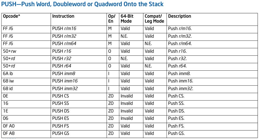
Here’s the Intel listing for push:
Hopefully you remember how to parse this table, but we’ll just be looking at the first three rows (a.k.a. those with r/m *) and considering the memory displacement operand. There are several classes of memory displacements, so let me list them here in Intel assembly form:
;; indirect register
push word  ptr [rbx]
push qword ptr [rbx]

;; indirect register with immediate 8-bit offset
push word  ptr [rcx + 0x12]
push qword ptr [rcx + 0x12]

;; indirect register with immediate 32-bit offset
push word  ptr [rsi + 0x12345678]
push qword ptr [rsi + 0x12345678]
We will be able to encode all of these by the end of this article. We’ll be using our helpful friend: the Intel Architecture Manual.
Here’s the table we’ll be referencing.
Last time we talked about two-register forms of instructions, but this will be easier when using PUSH because it only takes one instruction. Let’s do something easy and use the table for PUSH and the above table to encode push rax. We know that there’s the ModR/M byte with the following structure: 2 bits for the mode, 3 bits for a register, and another 3 for the R/M information. As it turns out, the first set of three bits are often used to encode more instructions while keeping the same opcode as a way of compressing the encoded instruction stream.
As I wrote in the previous post, the same instruction may be represented with different bytes, so if you encode push rax with an assembler, you may get 50. (Note: this corresponds to the 50 + rd row in the encoding table. Get the register you want from the registers listed in the fourth row on the table above and add the number aligned to it on the right to 50. For example, if you want push rbx, get the value from the ebx row (0b011 or 3) and add it to 50)
Though, one can also encode it with 0xff 0xf0. I’ll be explaining this one because it uses the ModR/M byte:
0xff - push opcode
0xf0 - 0b1111 0000
         MMxx xrrr

M - 0b11  - operand is a register
x - 0b110
r - 0b000 - rax register
Where is the “x” value coming from? It’s the /6 in the opcode above. It’s a long explanation but there’s a lot of implicit information there. Now, what if we changed the “x” value? If we changed it to 0b000, we get inc eax. It doesn’t work for every value from 0 to 7 but you can use an x86 instruction reference or the manual.
Now, we can actually work on this instruction. We’ll start with the first pair and the decoded ModR/M:
push qword ptr [rbx] - 0xff 0x33
push word  ptr [rbx] - 0x66 0xff 0x33

0x33 - 0b0011 0011
         MMxx xrrr

M - 0b00
x - 0b110 - push opcode extension
r - 0b011 - rbx operand bits
Everything but the “mode” bits should be clear. The “mode” represents how we’re accessing memory. In this case, we’re accessing the memory location in rax, so if the value in rax is 0x123456789abcdef0, then we will be accessing the quadword beginning at 0x123456789abcdef0. You’ve probably noticed that the word version of the operation is the same as the quadword version, prefixed with 0x66. This byte is called an “operand-size override prefix.” It basically tells the CPU to change the size of the operand. In this case, we override the size from a quadword to a word, but this changes depending on the operation.
I will also introduce the “address-size override prefix,” 0x67. In this case, it gets used to encode an operation like push qword ptr [ebx] (notice that rbx changed to ebx to indicate that we want to access memory with a 32-bit register. You can choose to use it because it’s there) to 0x67 0xff 0x33. What if we also add the 0x66 prefix (0x66 0x67 0xff 0x33)? Then, we get push word ptr [eax]. The prefix order doesn’t matter. You also encode this operation with 0x67 0x66 0xff 0x33.
It’s time to encode push qword ptr [rcx + 0x12]. This uses memory displacement mode 0b01, which means “use a register’s value and add a 8-bit displacement). We get this encoding: 0xff 0x71 0x12. Try out getting the second byte. The third byte is just the 8-bit displacement. If we want the word version, we simply add the “operand-size override prefix.”
How about push qword ptr [rsi + 0x12345678]? This one uses displacement mode 0b10, or “use a register’s value and add a 32-bit displacement.” This gets encoded to 0xff 0xb6 0x78 0x56 0x34 0x12 for similar reasons as above.
And now we’re done with the first type of memory displacments. You’ll notice the memory displacement contains entries with dashes. Those represent more complex memory displacment modes, which requires another byte called the SIB byte. Next time we’ll discuss it!


